J.R. Bircha and F.J.J. Clarkeb
aJB Research, 9 Clifton Terrace, Cliftonville, Dorking, Surrey RH4 2JG, UK
bDivision of Electrical Science, National Physical Laboratory, Teddington, Middlesex TW11 0LW, UK
Introduction
This work presents a comprehensive and logically ordered list of categories of ordinate error that can occur in conventional Fourier Transform Spectroscopy (FTS), many of which have not been cited before. Most of the items in the list are annotated with Notes giving causes or consequences that may not be widely known. The list evolved as part of a programme to provide reference standards of transmittance for the calibration of Fourier transform spectrometers, as it was soon realised that a knowledge of the possible sources of error was an essential precursor to finding out which ones are significant in such work and how they might be handled.
FT spectrometers are a class of analytical instruments of significant relevance to Quality Assurance for the chemical, pharmaceutical, food and other industries. Inspite of this importance, no transmittance standards calibrated to a known absolute accuracy have been available hitherto. Such artefacts are now available from NPL1 in the form of optical glass filters with a range of transmittances for checking mid-infrared grating and FT spectrometers. The transmittance of these filters have been established with overall uncertainties of order ±0.1 %. Thus, systematic effects which contribute at the ±0.03 % level of uncertainty are relevant to this work on reference standards. This infrared-based programme has developed from earlier work on the metrology of ultraviolet, visible and near infrared measurements.2
For clarity, only the simplest type of measurement is considered, that of the regular transmittance of a nominally plane parallel solid sample of no more than a few mm thickness, as this is the most basic and also the commonest of the possible uses of FT spectrometers. This restriction avoids the need to include other possible sampling errors that can arise with the less common measurement geometries of solids, or with liquids or gases in cells of various configurations. Guelachvili3 has considered systematic effects in the recording of interferograms in the context of high resolution gas phase FTS. For the same reason measurements of such properties as diffuse transmittance, regular or diffuse reflectance or ATR are not covered. Again, no attempt is made to cover the various hyphenated categories of FTS. In addition to the intrinsic errors caused by the instrument, technique or sample, extrinsic errors induced by human agency are also considered.
No attempt has been made in this short publication to quantify the errors. Many will not apply in any particular measurement situation, while those that do may vary in significance from being marginal to having a noticeable effect, as they will be dependent on the details of the instrumental design, its fabrication, its alignment, its control software and any possible deterioration in the field.
Classified list of categories of error
Non-ideal properties of the spectrophotometer
- Non-linearity of the detector, its analogue circuit or its ADC.
Note: The detector may be linear in response for smaller openings of the Jacquinot Stop but become non-linear for larger openings. This is common with cooled detectors.
- Non-linearity of the drive mechanism for path difference.
- Incorrect location of the position of zero path difference, e.g. due to a poor algorithm or inadequate set of samples used for this.
- Inadequate phase correction.
Note: Several different phase correction algorithms are in common use. They may not always give the same spectrum from a given interferogram. Further, the presence of a sample may alter the required correction, yet the background interferogram is normally used for a common correction applied to both sample and background transforms. This problem does not affect the calculation of the modulus or power spectrum from the cosine and sine transforms, which give real and imaginary parts of the immediately derived spectrum (see Note to Item 40).
- The instrument needs (or uses) a large Jacquinot Stop for a given measurement, due to its poor design (or control software).
Note: This gives trouble with skew rays and perhaps with detector non-linearity or sample heating. Skew rays give an erroneous wavenumber scale for each ray, they require different phase corrections and they also have variegated positions of zero path difference giving pseudo-coherence problems.4,5 In cases where large-NA aspheric collimator/anti-collimator mirrors are used, a large Jacquinot Stop leads to significant wavefront aberrations for the outer regions of the stop, giving more of these problems. These effects will be altered by the presence of a real sample, so that the calculated spectral transmittance will have ordinate and wavenumber errors.
- Aberrations introduced by the interferometer collimator mirror.
Note 1: Poor optical design or fabrication give rise to skew rays, which cause wavenumber and ordinate errors for the reasons given in the Note to Item 5. However, the warning given there to the increased effects found with large-NA aspheric mirrors refers to perfectly formed optics. This Note refers to imperfectly formed mirrors, so that even with a small Jacquinot Stop there will be skew rays. The larger the NA and the greater the off-axis angle, the more critical is the perfection of figure required.
Note 2: Even with a perfectly formed mirror and a small Jacquinot Stop, an incorrectly set off-axis angle will cause skew rays, giving rise to wavenumber and ordinate errors for the reasons given in the Note to Item 5. The larger the off-axis angle and the larger the NA of the mirror, the more closely must the actual off-axis angle match that of the mirror design.
- Effects of differences between the optical paths in the interferometer used by the measuring beam and those used by the HeNe laser radiation for monitoring the sampling of the interferogram.
Note: As most infrared optical transmitting components, e.g. the coated beam splitter, are opaque to visible HeNe radiation, special arrangements need to be made to allow it to be propagated in the interferometer. This may involve propagation at the side of the measuring radiation beam or at the centre of the measuring beam, but using different coatings and/or optical media in either case. It cannot be taken for granted that the monitoring beam optical surfaces are coplanar with the corresponding ones for the measuring radiation, as inserted elements and/or different coatings are involved. The wavenumber scaling as well as ordinate values will be affected if the path difference for measuring radiation does not agree with that for HeNe monitoring radiation. The presence of skew rays in the measuring radiation will compound the problem (see Note to Item 5).
- Timing and/or distance instability in the onset of each sampling point of the interferogram causing distortions in wavenumber and ordinate values.
Note: Within a scan this causes local distortions of ordinate and of wavenumber in a raw spectrum, but between scans causes errors in the calculated spectral transmittance.
- Opto-mechanical instability and drift, causing ordinate and wavenumber distortions (see Note to Item 8).
- Source and/or detector instability and drift.
Note: Within a scan this causes local distortions of ordinate in a raw spectrum, but between scans causes errors in the calculated transmittance.
- Electronic noise (especially around a local maximum or minimum), instability and drift.
Note: The common practice of co-addition of interferograms is valid for the reduction of true noise (very short term random fluctuations). However, it is not valid for dealing with instability and drift, as the practice produces a loss of interferometric modulation analogous to optical pseudo-coherence effects.4,5 This also jeopardises the multiplex advantage of FTS. A better practice is to average spectra (see Notes to Items 41 and 42).
- Short-term electromagnetic, acoustic or vibrational interference with instrument function (see Note to Item 11).
- Long-term repeatable electromagnetic, acoustic or vibrational interference with instrument function.
Note: Unlike the situation with Item 12, this problem may be correctable or partly correctable by recording a blocked-beam interferogram and subtracting the transformed “zero-offset” spectrum from sample and background spectra prior to taking their ratio. This will apply if the interference contribution is phase-locked to the interferogram recorded, e.g. by the electrical supply timing.
- Conventional algorithm used for direct calculation of modulus or power spectrum, leading to rectification of random noise at some of the data points in very low-transmittance portions of the spectrum, which should show a proportion of negative values (see Item 40).
- Interferometer alignment deficient, leading to pseudo-coherence effects,4,5 weak interferograms, compromised phase corrections and local distortions in the results.
Note: Poor optical figure of any of the components of the interferometer or non-linearity of the drive mechanism (Item 2) can contribute to ambiguities in finding the optimum alignment. Even where the alignment procedure has been successful, the interferometer may become misaligned subsequently.
- Satellite reflections from the beamsplitter producing satellite interferograms, which may overlap the sampled region of the main interferogram.
- Spurious spectral values computed due to a combination of poor software scaling strategy and high outof-range values derived in the Fourier transform.
Note: This tends to arise when integer arithmetic is used for computational speed and when gas discharge sources or narrow-band interference filters are being measured. When the sample spectrum has isolated narrow strong emission or transmission features, these can be orders of magnitude above the average level of the sample spectrum. The supplied scaling strategy that is satisfactory for normal applications may lead to out-of-range values under these special conditions.
- Inadequate apodisation method available to suit the application.
Note: Currently used algorithms have poor convergence to zero outside the required passband. This can cause spurious satellite peaks and also effects equivalent to those produced by “straylight” in a grating spectrophotometer, especially where the tails of the passband have only positive features.
- Distortion of spectral measurements due to water vapour and carbon dioxide not being fully purged and no true double-beam chopping being practicable.
- Inter-reflection between the interferometer reflectors and the Jacquinot Stop or the pre-interferometer optics or the source (see Figures 1 and 2).
Note 1: This produces double frequency modulation and hence an added satellite spectrum shifted with doubled wavenumbers. This can have a significant effect on background and sample spectra and the effects fail to cancel out in calculating the transmittance when the sample is spectrally selective. Higher order inter-reflections of this type could possibly occur with tripled or quadrupled wavenumber shifts, but the effects would be much weaker than for the doubled wavenumber case.
Note 2: The meaning of Items 20 to 26 may be clarified by reference to Figures 1 and 2 and their captions. These seven categories of inter-reflection usually involve the radiation passed through the system from the source, and for simplicity Figures 1 and 2 only deal with components of radiation originating from the source. However, with a cooled detector the radiation emitted from the detector window, bezel or casing or from the post-sample and pre-sample stops or apertures or especially the Jacquinot Stop may also make a significant contribution to these items. This is referred to as a “detector port radiation effect” and its effect is more marked towards the low wavenumber end of the spectral range.6
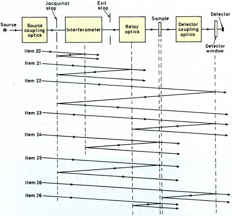
Figure 1. Schematic diagram of a generic Fourier Transform spectrometer to explain the seven logically distinct categories of interreflection effect referred to in Items 20 to 26 of the text. The last one shown (Item 26) has two subgroups of causes illustrated. Hypothetical positions of the reflecting surfaces causing the problem (which might lie outside the beam cross-section) are indicated by vertical dashed lines. Some likely locations are the detector element, the detector window, any sample compartment windows of an evacuated system, the exit stop of the interferometer, the reflectors at the ends of the interferometer arms, the Jacquinot Stop or the source itself. This diagram does not cover other inter-reflection effects involving emitted radiation, such as the detector port radiation effect.6
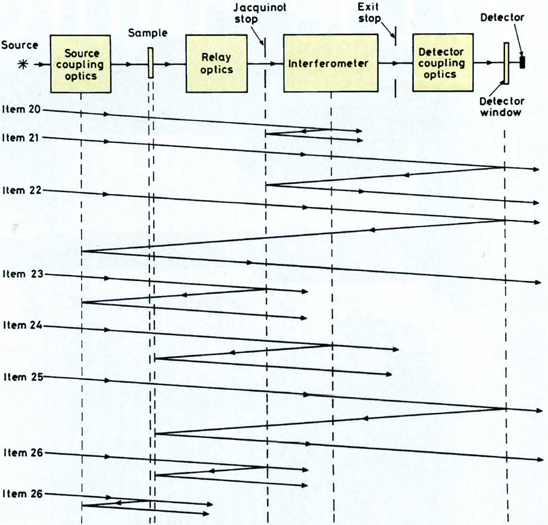
Figure 2. As for Figure 1, but illustrating an alternative configuration of generic Fourier Transform spectrometer with the sample preceding the interferometer, which affects the location of inter-reflection effects referred to in Items 20 to 26 of the text.
- Inter-reflection effects between optical components before and after the interferometer, but not involving the sample or beyondsample optics (see Figures 1 and 2).
Note: This produces triple frequency modulation and hence an added satellite spectrum shifted with tripled wavenumbers. The effects fail to cancel out in calculating the transmittance when the sample is spectrally selective. A higher order inter-reflection of this type is also possible, with quintupled wavenumber shifts, but this would usually be very weak.
- Inter-reflection effects through the sample position causing further passes through the interferometer (see Figures 1 and 2).
Note: This produces an added satellite spectrum shifted with tripled wavenumbers. With a higher order of inter-reflection a much weaker added component with quintupled wavenumbers is possible.
- Inter-reflection effects through the sample position but not involving the interferometer (see Figures 1 and 2).
Interaction of non-ideal instrument and sample properties
- Inter-reflection effects between the sample and the interferometer reflectors (see Figures 1 and 2).
Note: This produces an added satellite spectrum shifted with doubled wavenumbers: its sign and magnitude is affected by the uncertain phase difference between its interferogram and the proper interferogram.
- Inter-reflection effects from the sample causing further passes through the interferometer (see Figures 1 and 2).
Note: This produces an added satellite spectrum shifted with tripled wavenumbers. With a higher order of inter-reflection a much weaker added component with quintupled wavenumbers is possible.
- Inter-reflection effects from the sample not involving the interferometer (see Figures 1 and 2).
Note: If the sample precedes the interferometer the inter-reflected components alter the ray pattern in the interferometer (see Note to Item 33 for the consequences).
- Effects caused by polarisation bias produced at the sample (either intrinsic or due to the geometry of presentation) interacting with the polarisation bias of the instrument.
- Radiative heating of the sample causing emission which is not ignored by the instrument.
- Radiative heating of the sample causing thermochromism, and hence altering its absorption properties.
- Decrease in transmittance caused by oblique sample presentation, due to absorption and reflection losses increasing with obliquity.
- Decrease in transmittance caused by converging/diverging sample beam, due to absorption and reflection losses increasing with obliquity.
Effects of non-ideal properties of the sample
- Inter-reflection effects within the sample, including the formation of resolvable interference fringes (channel fringes).
Note: The presence of such interference fringes may be regarded as a genuine feature of the sample’s transmittance spectrum if the sample, or a layer on it causing the interference, is thin enough for the order of interference to be low, as the fringes then always have approximately the same positions of maxima and minima instrument-to-instrument due to not being affected much by the angle of incidence. For thicker samples or layers the order of interference is higher and the positions of fringe maxima and minima (and indeed the fringe contras t) is more instrument dependent due to the greater influence of angle of incidence and the solid angle of irradiation.
The higher the instrumental spectral resolution, the thicker the sample that can show resolved interference fringes, and the less predictable the fringe position for a real instrument. In these cases the fringes can be a nuisance and be regarded as a spurious addition to the underlying spectrum. In such circumstances a lower resolution spectrum which does not resolve the fringes may be preferred, or the fringes may be removed post hoc by other means.
- Optical focusing power introduced by the sample.
Note: Items 33 to 38 will generally produce greater effects when the sample precedes rather than succeeds the interferometer, due to the ray pattern in the interferometer being altered in the former case (with an increase in “skewness” of rays on average, if the instrument is well aligned with no sample present) but not in the latter case. Additionally in the former case a slightly different set of rays passes through the Jacquinot Stop. In the latter case a different set of emerging rays reaches the detector, and the effects are different. In the former case the ordinate and wavenumber scaling and even passband may be affected, but in the latter case only the ordinate values can be affected.
- Optical wavefront aberration introduced by the sample, e.g. due to poor figure or refractive inhomogeneity (see Note to Item 33).
- Beam deviation introduced by the sample, e.g. due to wedged shape or graded refractive index (see Note to Item 33).
- Change of pathlength due to a thick sample in a convergent or divergent beam (see Note to Item 33).
- Scattering by the sample (see Note to Item 33).
- Diffraction or vignetting by the sample or its holder, or a difference between apertures near the sample position during sample and background scan, if either limits the throughput (see Note to Item 33).
Deficiencies of the measurement procedures
- Inappropriately large size of Jacquinot Stop selected, leading to effects of skew rays, detector nonlinearity, sample heating etc. (see Note to Item 5.)
- Incorrect choice of phase correction algorithm or of direct power spectrum calculation.
Note: The true power algorithm involves using cosine and sine transform of an interferogram, which are squared and added, and the square root is then taken. Its strength is that it returns the correct spectrum as it avoids the errors that can result with phase correction algorithms. The power algorithm has the disadvantage that double-sided interferograms are required, instead of the nearly single-sided ones that are sufficient for the phase correction method. This disadvantage disappears for low to medium resolution work where double-sided interferogrammes are normally used. In common practice there is a second disadvantage of the direct power calculation: in regions of very low spectral value, noise can be rectified, giving rise to positively biased results.
- Drift correction calculations carried out at the wrong level (interferogrammes) instead of the correct level (spectra).
Note: Averaging interferogrammes in the presence of drift produces a loss of interferometric modulation analogous to optical pseudo-coherence effects. The quantitative structure of the modulus spectrum of a shifted interferogram is unchanged. Hence spectra can be averaged validly.
- Poor strategy to minimise drift.
Note 1: An accurate measurement requires a sequence or sequences of three types of scan: background B, sample S and zero-offset Z (see Item 13). The optimum order in a sequence depends on the level of sample transmittance, but generally effective sequences of a minimum of four scans would have the general character of (S1–B–Z–S2) or (S1–Z–B–S2). For less demanding measurements the zero-offset scan might be omitted. This is the usual case in FTS.
Note 2: The common practice of using the latest background interferogram to derive the phase correction of any sample interferogram, until a new background interferogram is recorded and processed, will not give the best results with a drift correction strategy. Better practice is for the first sample interferogram not to be phase corrected and transformed until the local background interferogram of a sequence, as in Note 1, has been processed, so that the common phase correction used for the two sample and one background scans is applied to instrument conditions as similar as possible. Better still, every interferogram should use its own self-derived phase correction (though some commercial software will not allow this).
- Inappropriate drive-speed or scantime for the moving optical component. This needs to be compatible with the detector frequency response and sampling interval.
- Inappropriate sampling of the interferogram leading to spectral aliasing from above the Nyquist limit. (1, 2, 4, etc., monitor laser fringes per sample interval.)
- Inappropriate resolution selected.
- Inappropriate apodisation selected.
- Inappropriate choice of beamsplitter or detector (where a choice is available).
- Incorrect or badly-chosen angle of sample presentation.
- Inaccurate data-fit on the raw output spectrum from the Fast Fourier Transform to give the final output spectrum at rational integer-based wavenumbers.
Note: The raw output spectrum from the FFT will have the same number of values as the interferogram samples and these will be at irrational wavenumbers that occur at sub-multiples of those of the HeNe visible radiation used to control interferogram sampling. Certain sharp structures in the spectrum (perhaps in combination with the effects of noise) could cause some data-fitting algorithms to give anomalous values. This is less likely if zero-filling or other reliable methods are used to increase the number of data points for a given resolution.
- Non-linearity, zero-offset or scaling ordinate errors or abscissa offset errors in the VDU, hard-copy plotter or other graphical output device.
Note: These errors only arise where a graphical output device is used to judge an ordinate and/or abscissa value, e.g. when deciding the ordinate and/or abscissa value at a local minimum or maximum, or when judging values under noisy conditions.
Conclusions
The categories of possible systematic error surveyed in this paper cover the most significant that are found in FTS. The presence or absence of overall error when using any particular instrument can best be established through the use of transmittance standards calibrated to a known absolute accuracy.1 Where more than one source of error contributes significantly, the analysis and interpretation of discrepancies can become difficult. This is especially so for certain of the sources of error, such as those involving inter-reflected radiation passing back through the interferometer, where phase changes may cause a change of sign of the added contribution and the sign might change several times over the whole spectral range covered.
Nevertheless, a knowledge of the possible sources of error and their likely consequences is an essential pre-requisite to finding out which ones are actually occurring, so that a valid improvement to the technique or correction procedure can be developed.
Finally, it may be noted that current practice in FTS is still influenced by the historic shortage of the considerable computing power needed for carrying out FTS adequately. However, with the current availability of powerful state-of-the-art portable computers at affordable prices, better practices as implied in some of the Notes to the Items above have become practicable.
References
- Available from Division of Electrical Science, NPL. Contact: Dr F.J.J. Clarke
- F.J.J. Clarke, “High accuracy spectrophotometry at the National Physical Laboratory”, J. Res. NBS 76A, 375–403 (1972). https://doi.org/10.6028/jres.076A.036
- G. Guelachvili, “Distortions in Fourier spectra and diagnosis”, Spectrometric Techniques. Vol. II, Ch. 1, Ed by G.A. Vanasse, Academic Press, New York (1981). https://doi.org/10.1016/B978-0-12-710402-7.50007-1
- E.E. Bell, “The use of asymmetric interferograms in transmittance measurements”, J. Physique Colloq. 28(2), 18–25 (1967). https://doi.org/10.1051/jphyscol:1967205
- J.R. Birch, “Imperfect optical figure in Fourier transform spectroscopy”, Infrared Physics 30, 155–159 (1990). https://doi.org/10.1016/0020-0891(90)90026-R
- J.R. Birch and E.A. Nicol, “The removal of detector port radiation effects in power transmission or reflection Fourier Transform”, Infrared Physics 27, 159–165 (1987). https://doi.org/10.1016/0020-0891(87)90004-2

